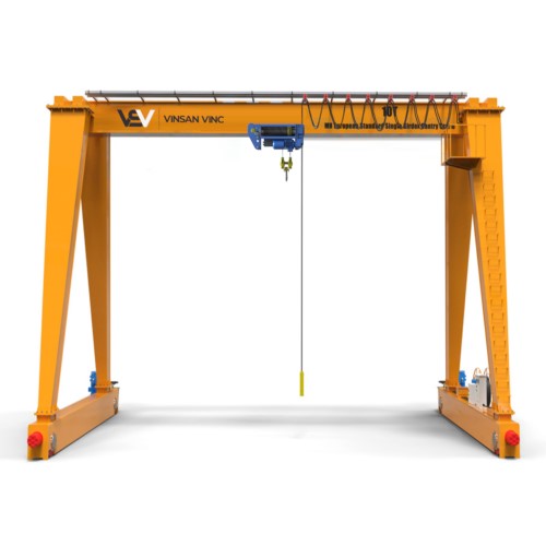
Crane Systems
Cranes are the hidden heroes that make it easy to move the heaviest loads in the toughest areas. Building a crane is no different than manufacturing any industrial machine. Like every machine group, it is a group of parts that enable a desired machine to work efficiently in the desired function. Energy is needed to bring the mechanical construction of a constructive machine to life. These hidden heroes are used with the needed energy by moving them with a command control. It is necessary to know or be asked in order to choose the crane suitable for the need in the desired function;
- Learning and knowing mechanical construction
- To learn and know the electric motor and the energy to be used
- To learn and know the command control system
- Learning and knowing steel construction
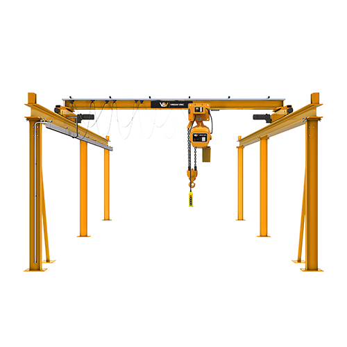
Crane Motion Systems
With cranes, loads are moved in 6 directions, that is, 3 axis.
- Vertical lifting and lowering movement with the Lifting System.
- Horizontal directional drive movement with trolley and bridge drive system.
- Rotation Horizontal rotation of my system.
- Brake system Lowering, traveling, holding and stopping function braking.
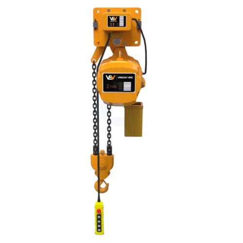
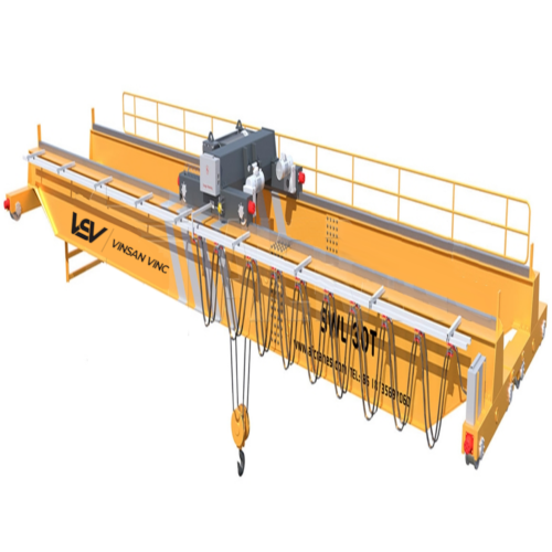
Crane Lifting System
- Wire Rope Hoisting System: It is a wide variety of round cross-section products that have high strength in small diameters, high flexibility, and low self-weight in response to the loads they carry. Steel ropes can be examined from TSE 1918/xx and DIN 3051 to DIN 3063 standards.
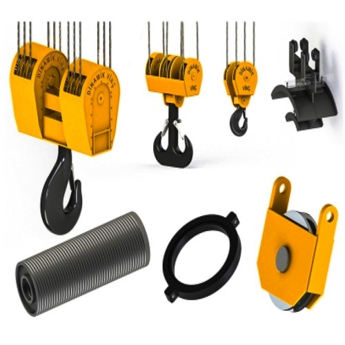
- Crane Rope Reels: They are constructions that are inclined in the same direction as the flow of the rope, which is placed on the reel core, which is generally manufactured from rural or steel casting or forging. Considering the driver group and rope type factor, the diameter of the pulley should be at least 10 times the diameter of the steel rope with which it will work. Choosing the right reel and rope prevents the rope from getting stuck or jumping out of the pulley during the lifting of the load, ensuring safe operation.
- Crane Hook: The most used products in cranes are hook sets. Hook kits consist of three constructions; The construction with the traverse, which brings together the pulley, hook, connecting pin, hook and rope reels, is created according to DIN 15400 standards. Hooks are available in 2 types of production, can be produced as free forging or die forging. The marking in the standards for free forging is (RF) and Die forging is (RS). If there is a safety catch on the hook, the letter (N) will appear next to these markings.
- Winch Drum: It provides the upward movement of the steel rope and the load by wrapping the rope around the drum. Steel ropes should be wrapped around the drum with helix grooves to prevent the possibility of accidents and unintended consequences. Smooth drum can be used in construction winches and structures with light loads but long lifting distance. Having vertical-like circular structures at the head of the drum is an essential safety structure that acts as a heel to prevent the rope from coming off. The calculation of these disc-like structures according to the safe handling standards of the rope is at least (2 x rope diameter) as the drum radius and height calculation.
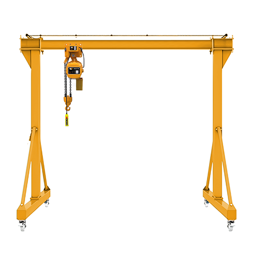
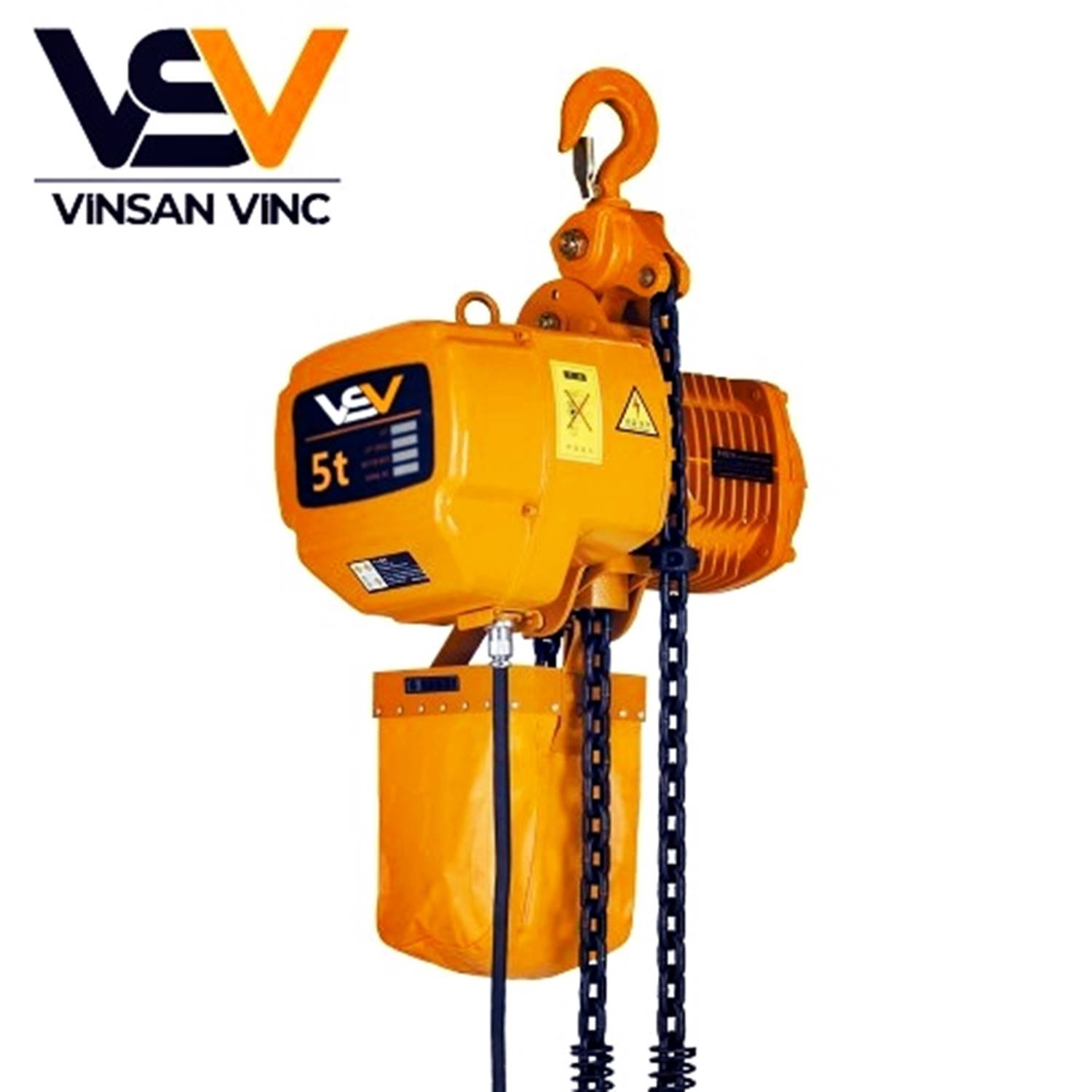
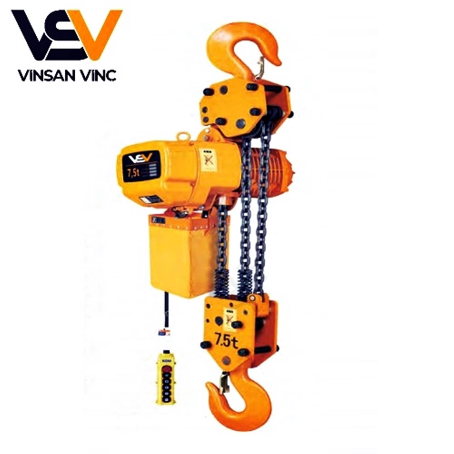
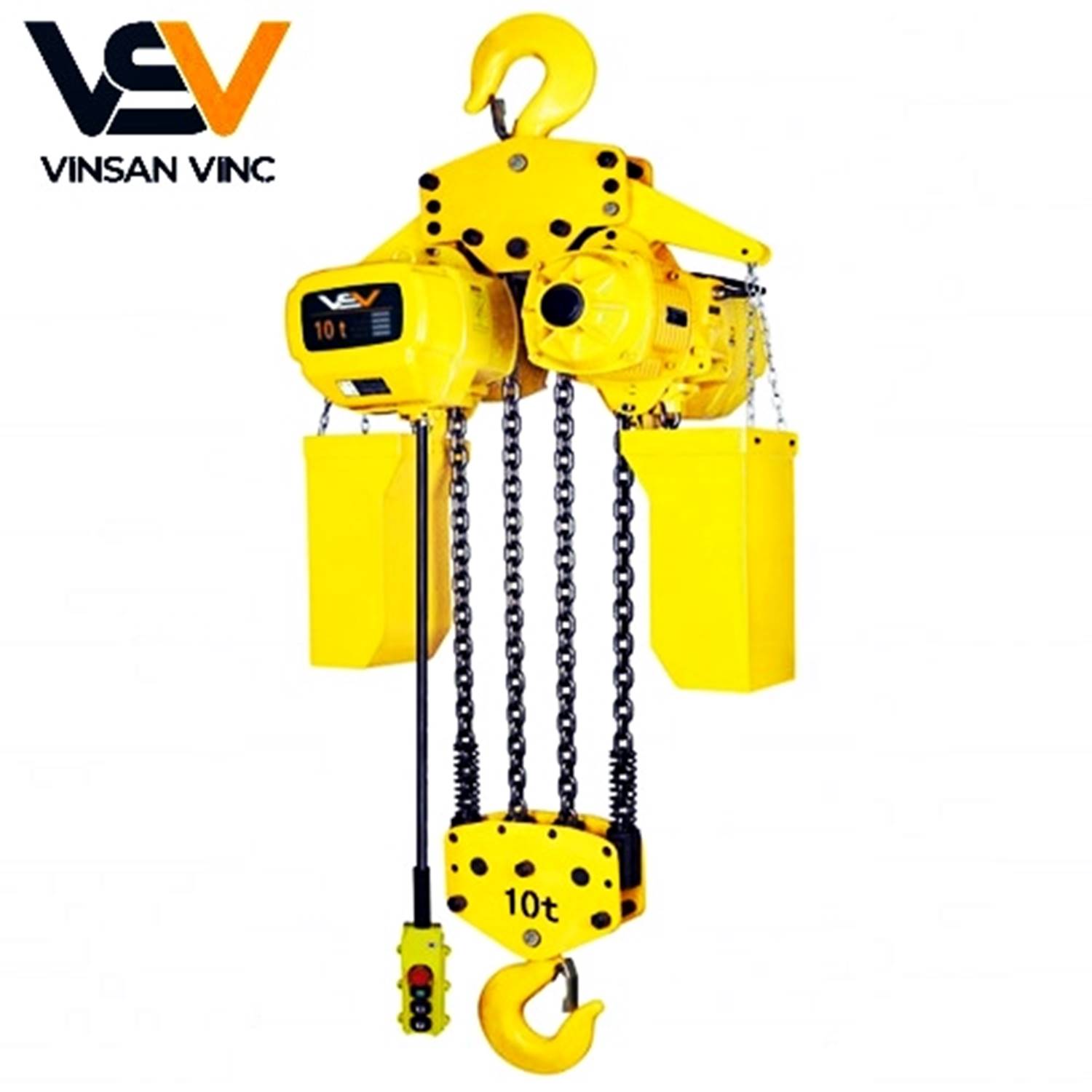
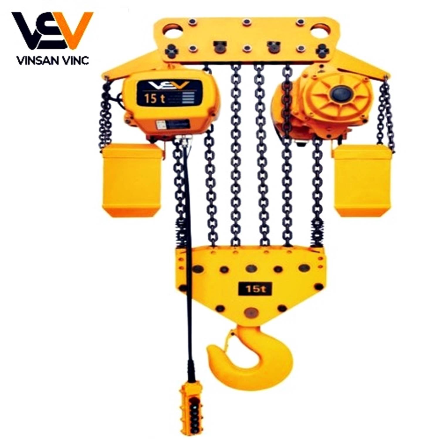
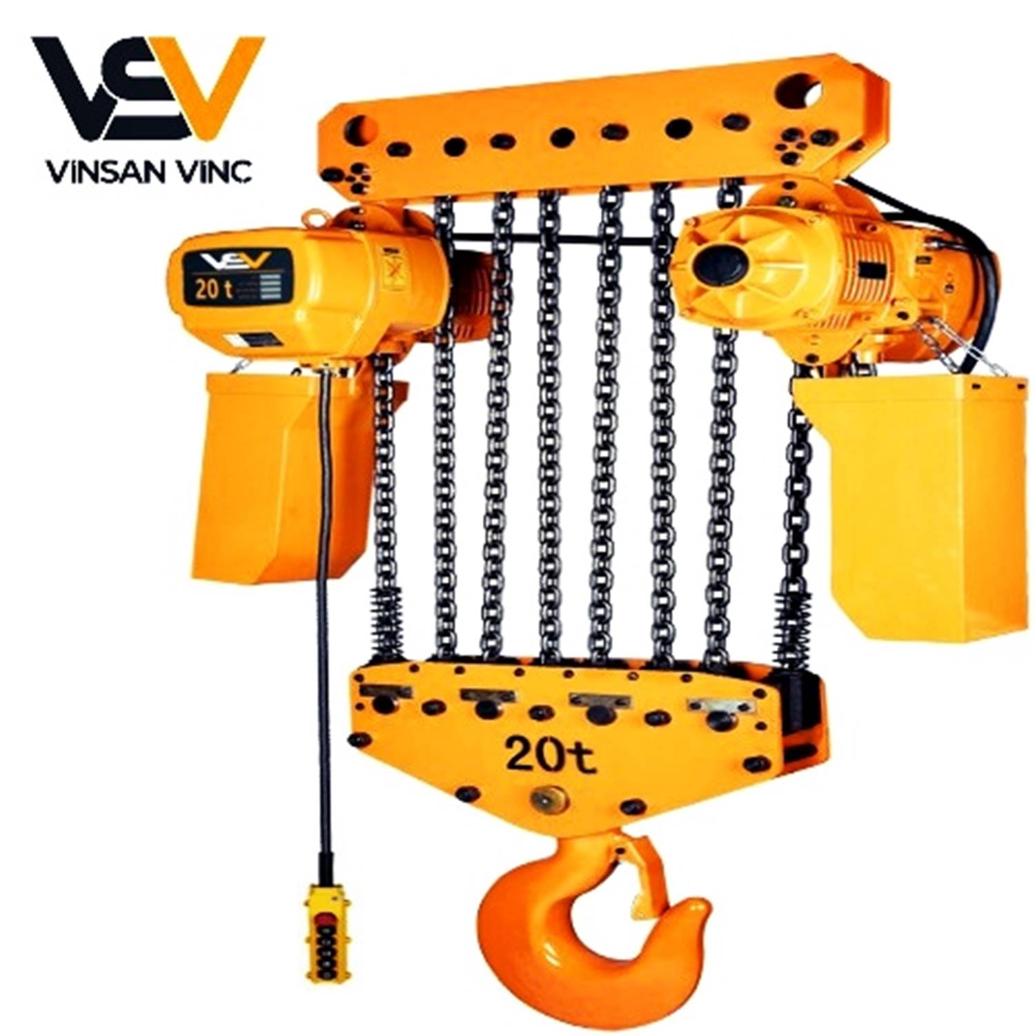
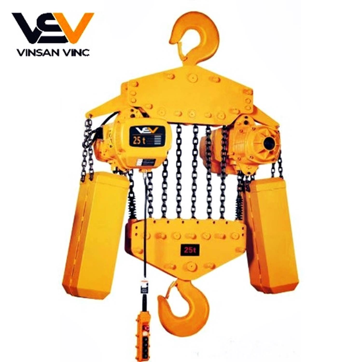
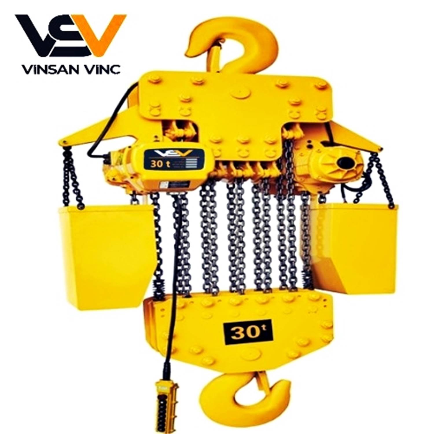
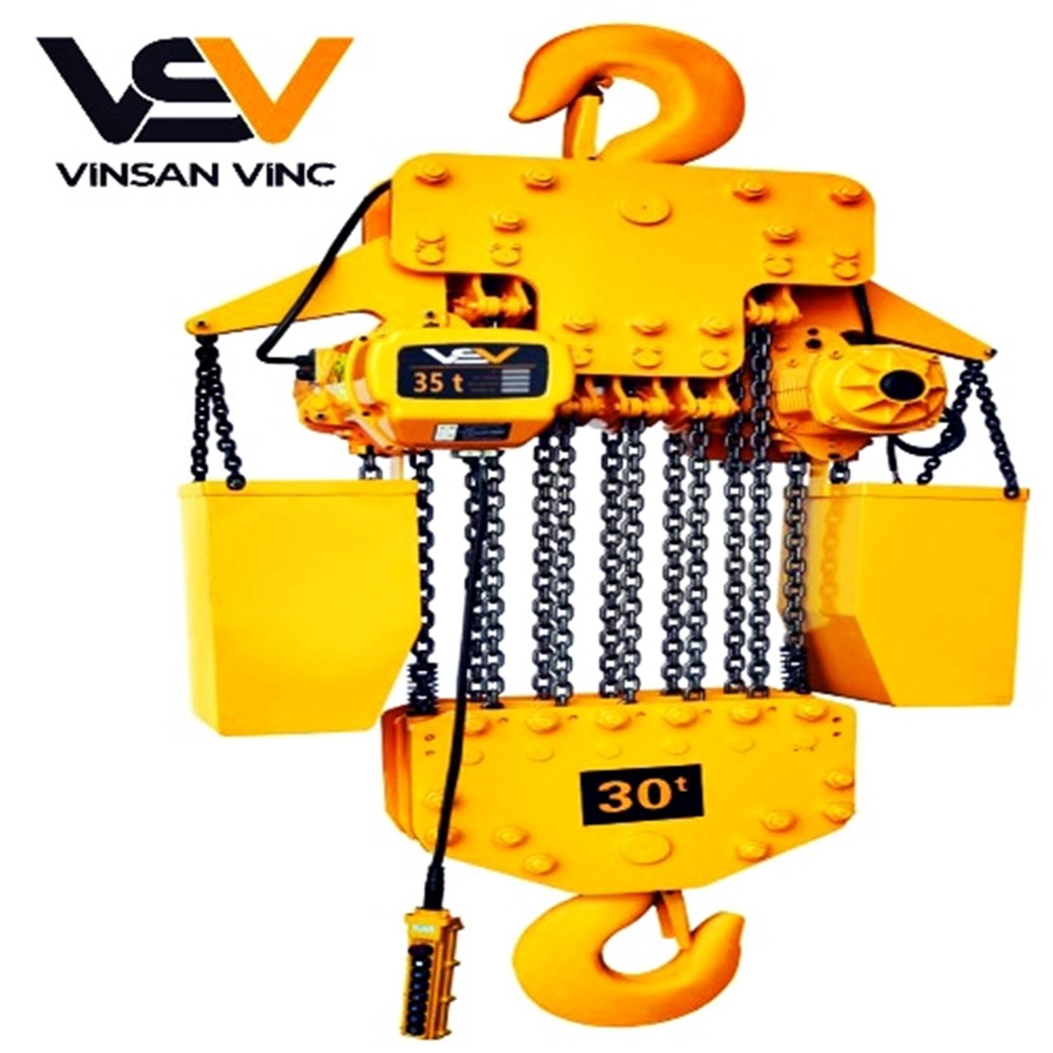
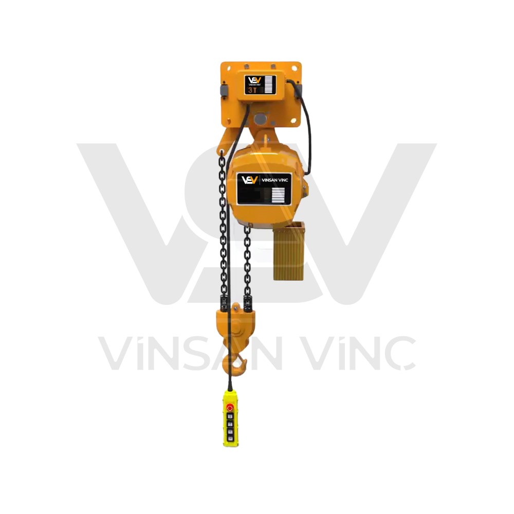
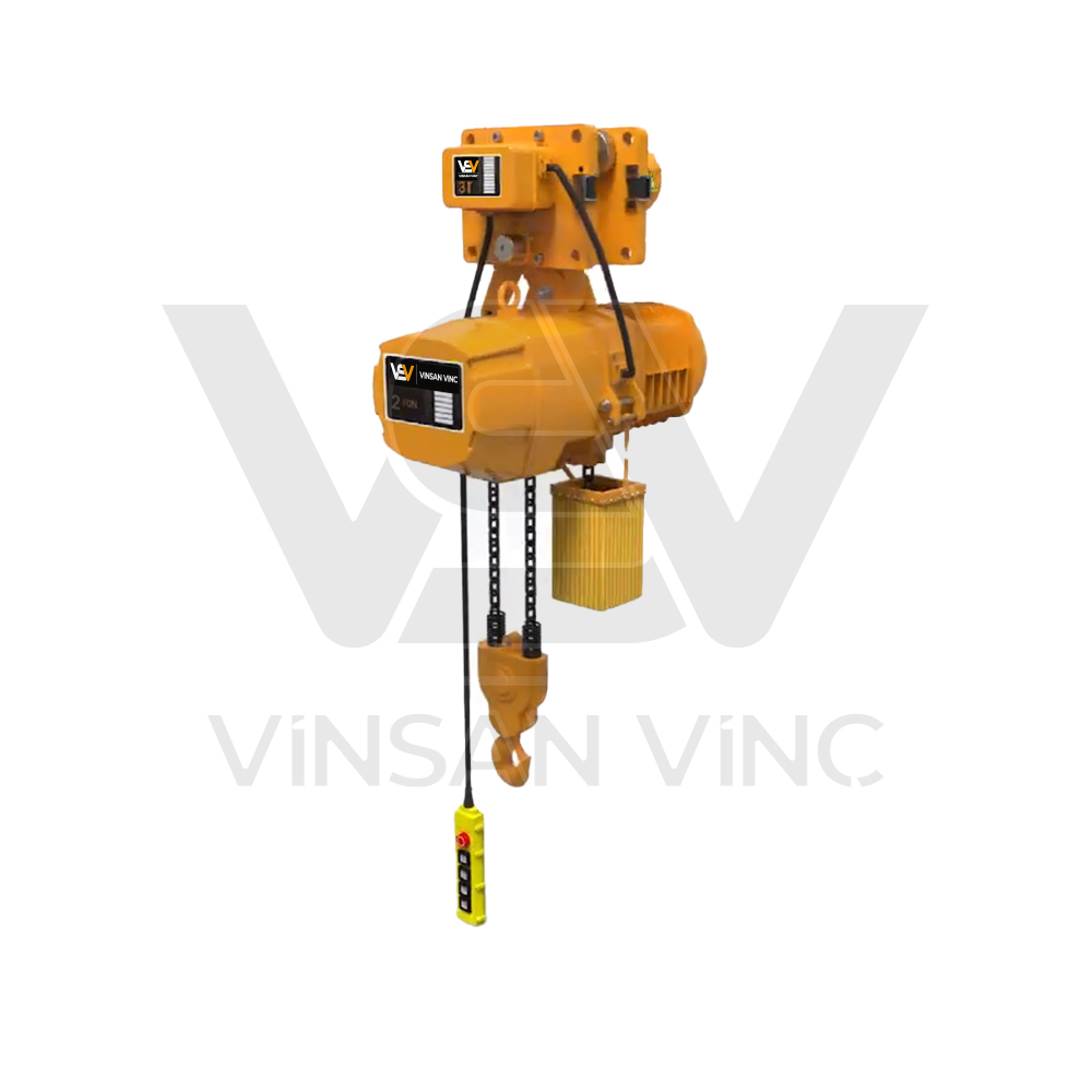
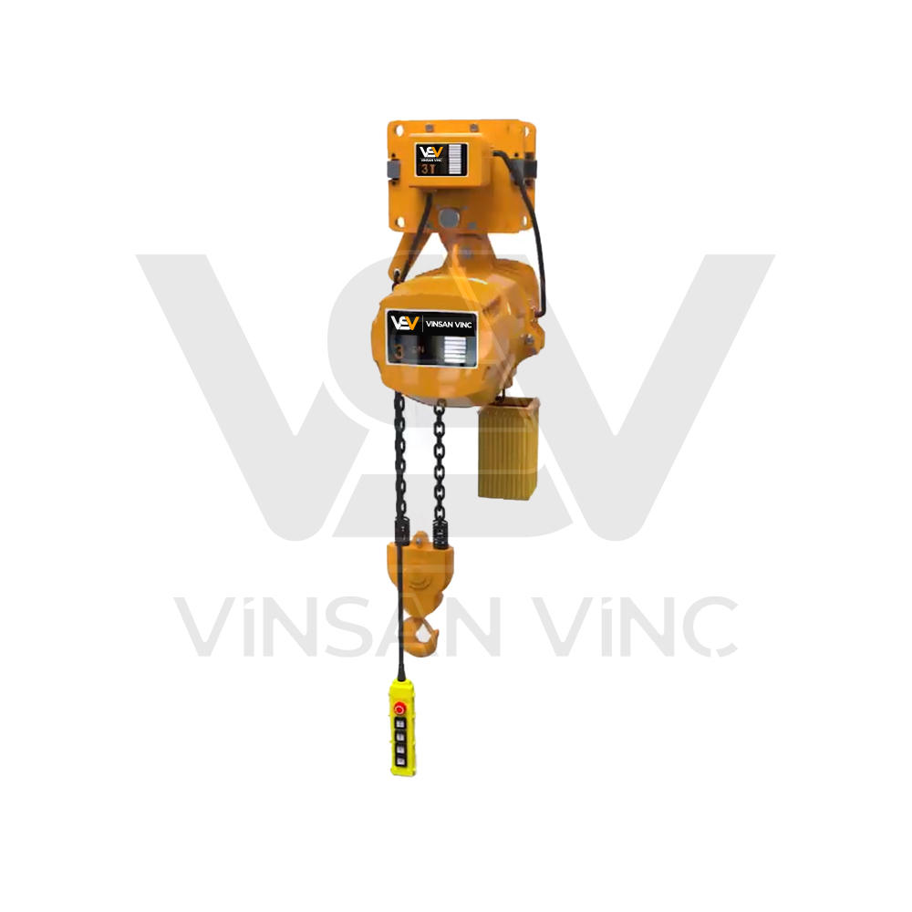
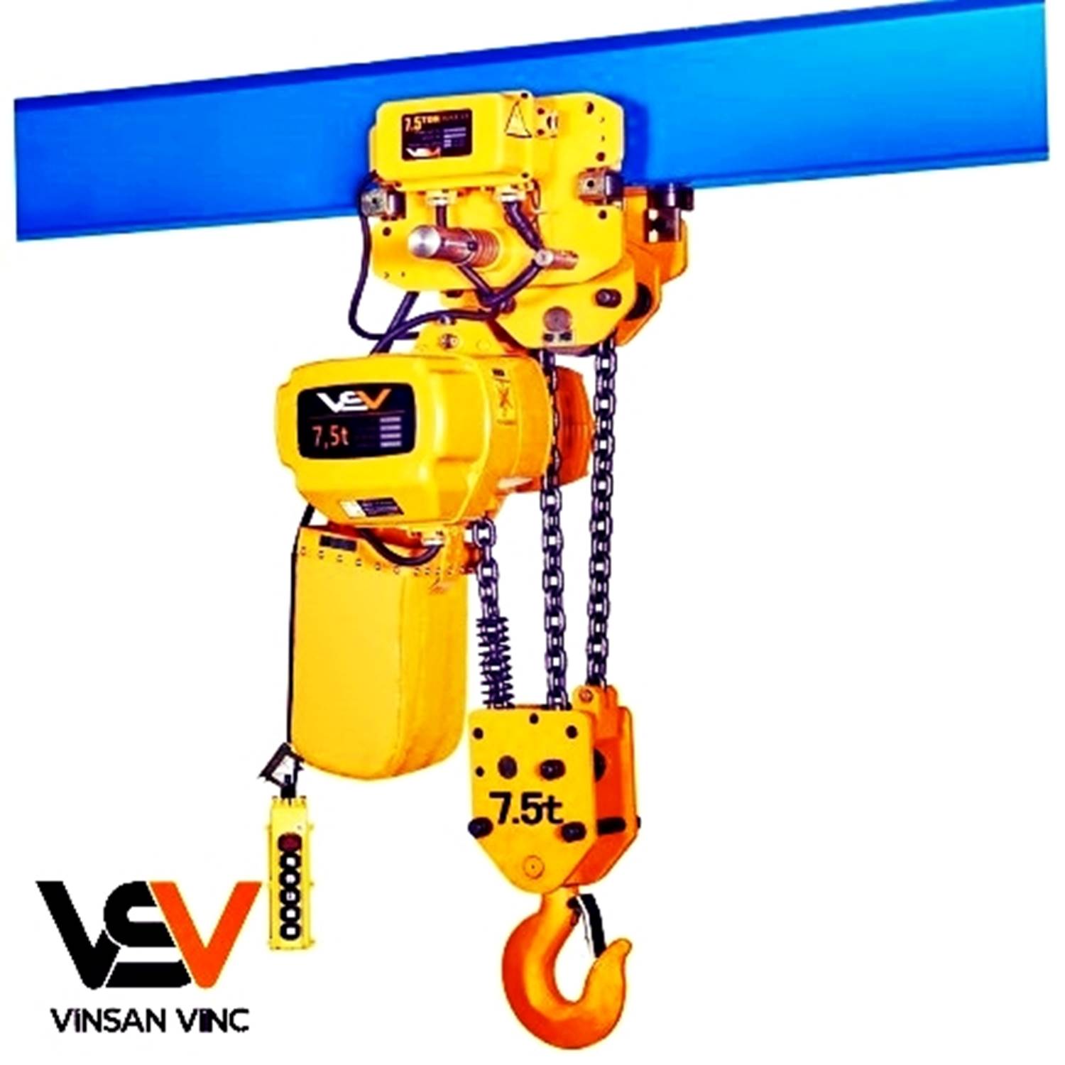
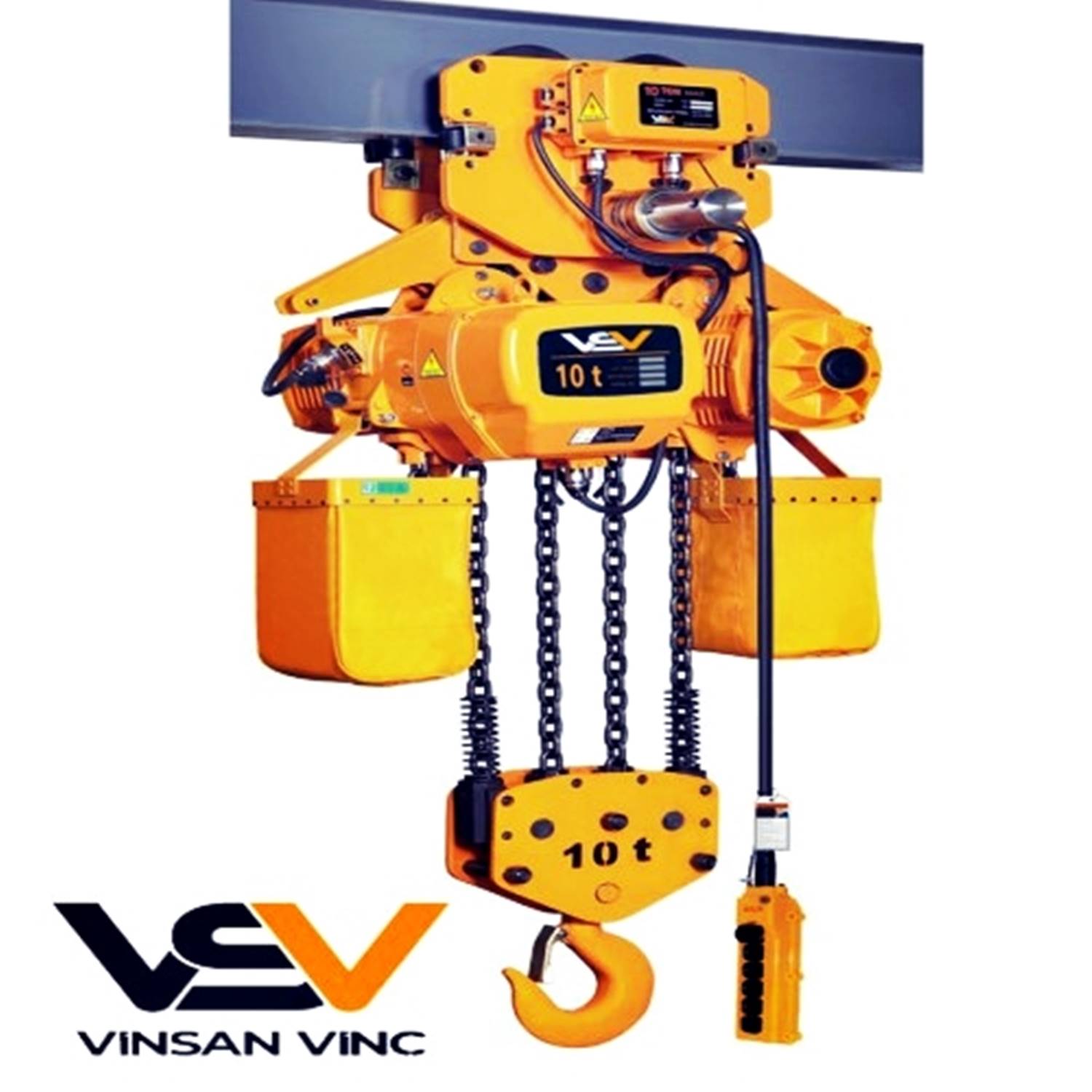
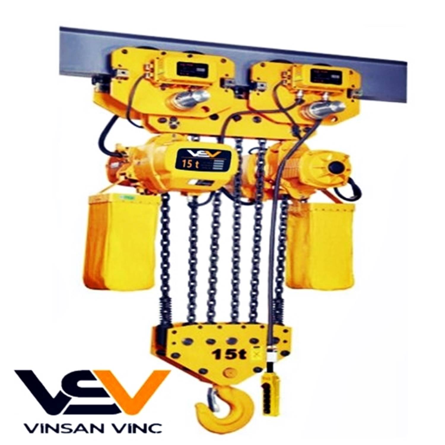
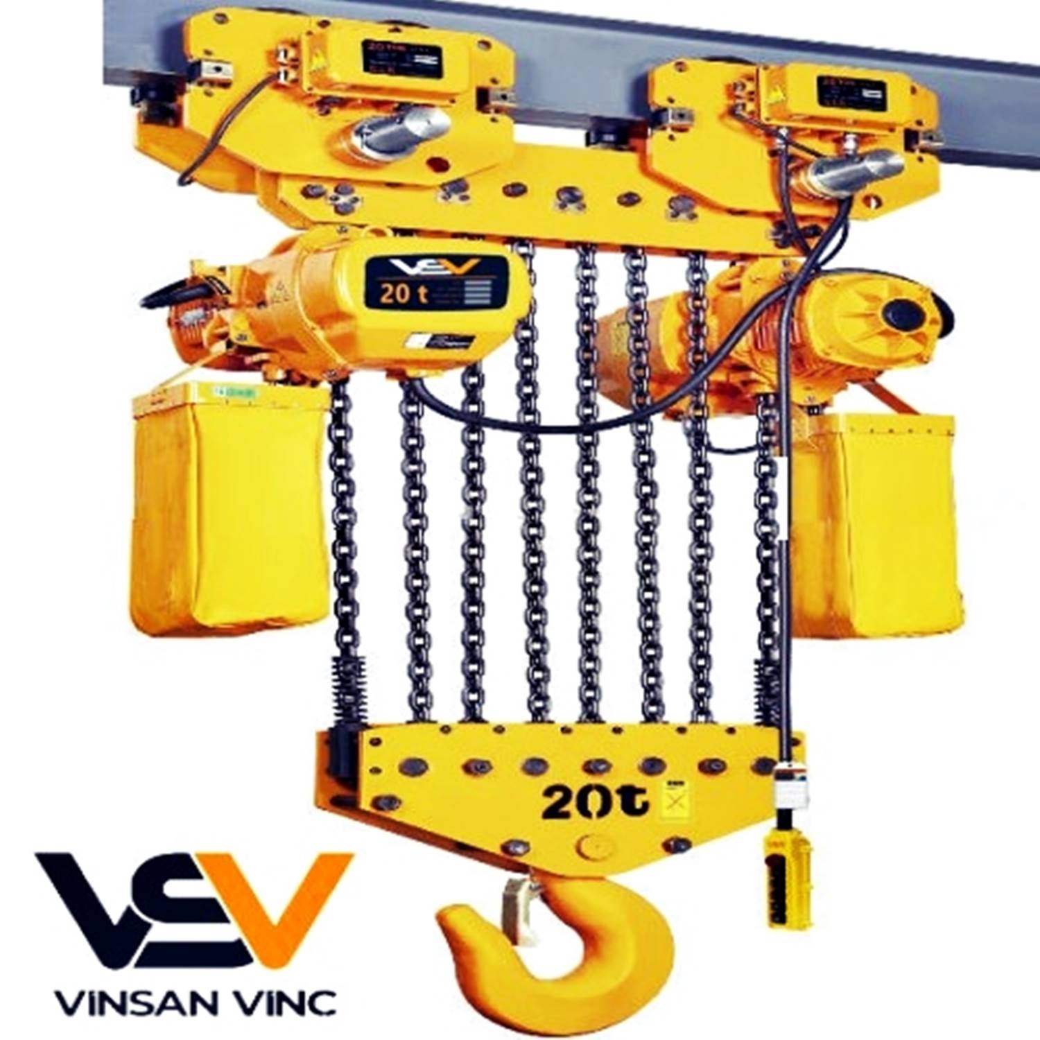
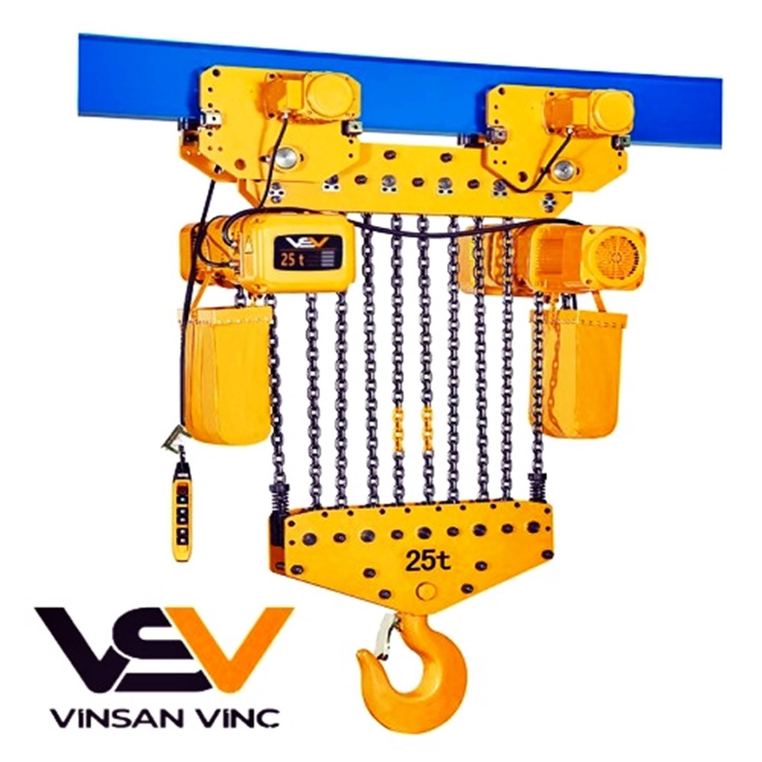
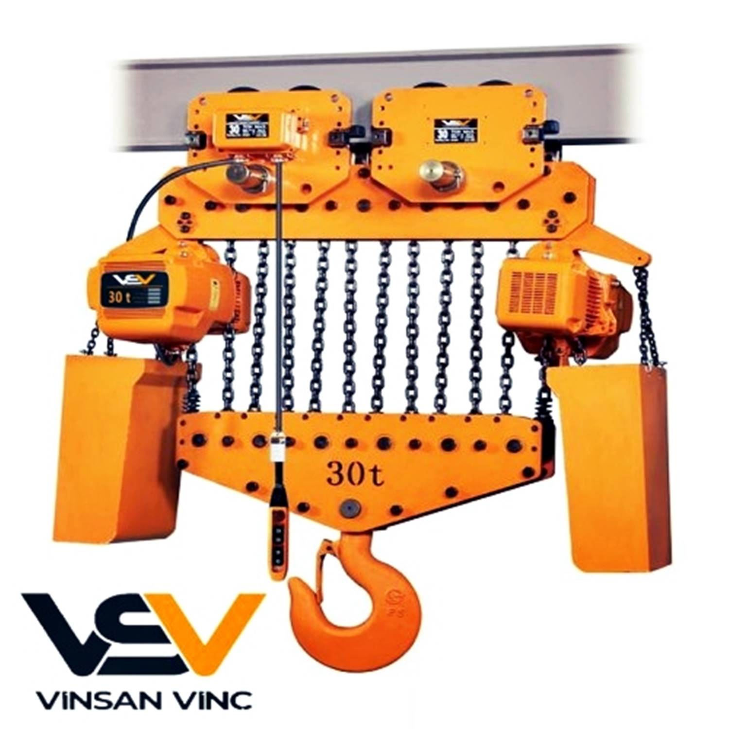
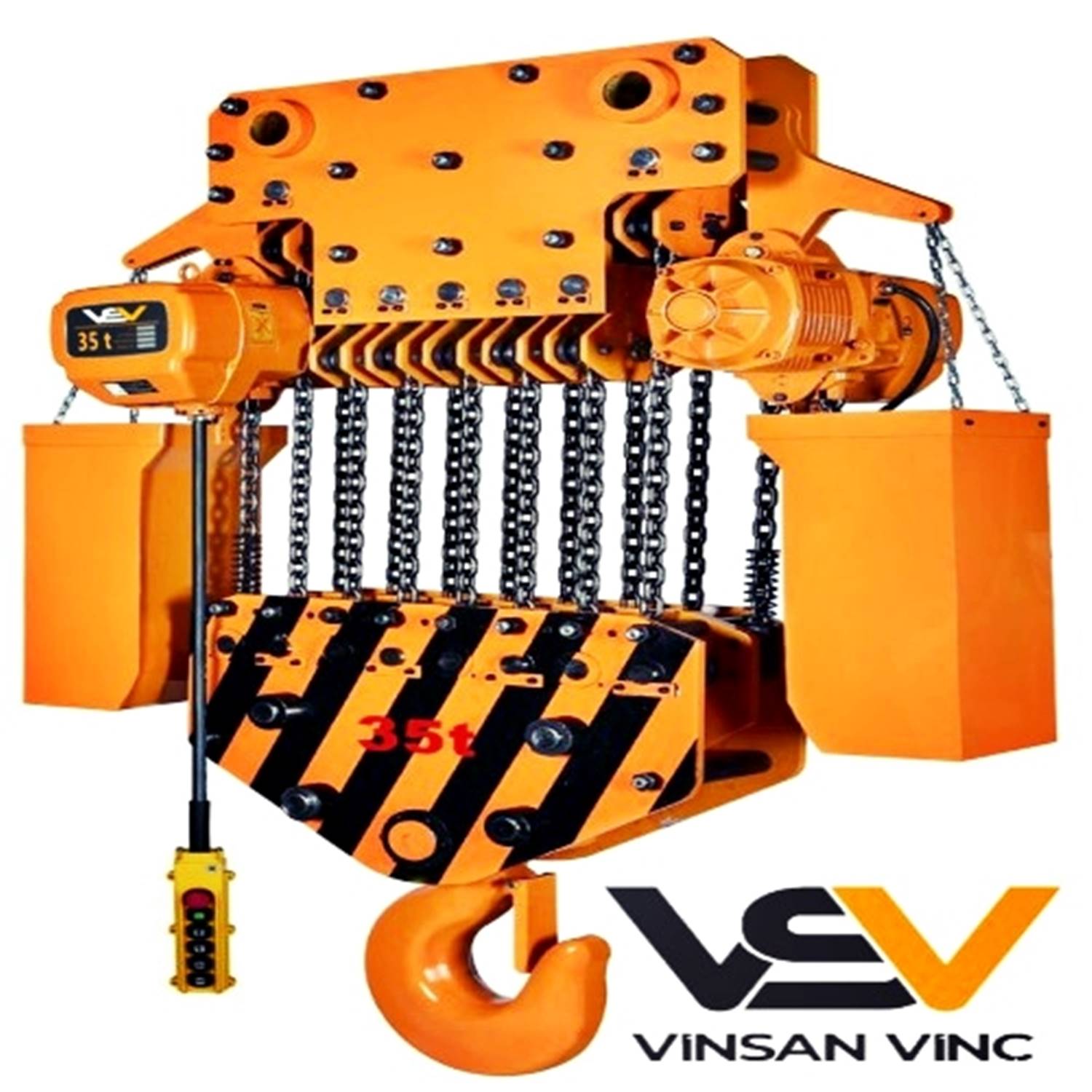
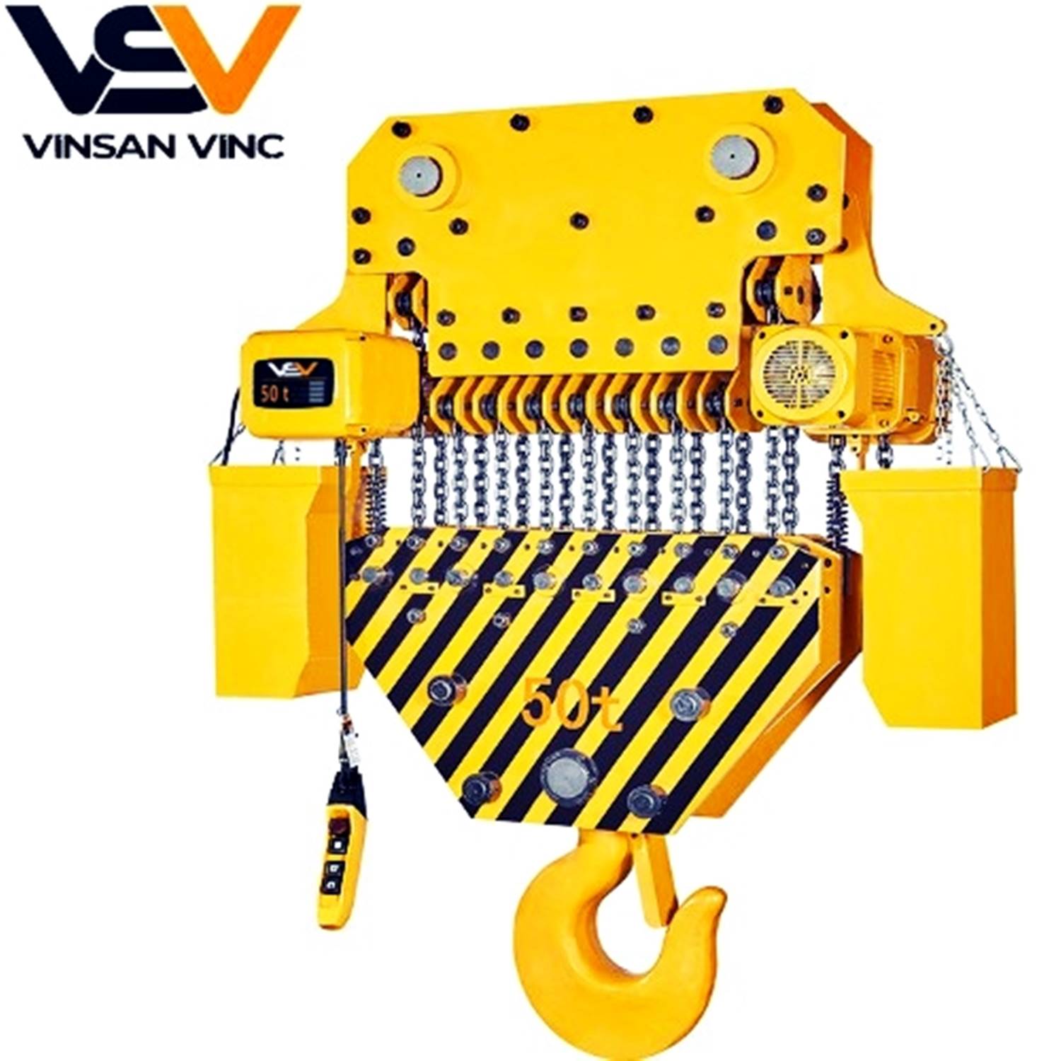
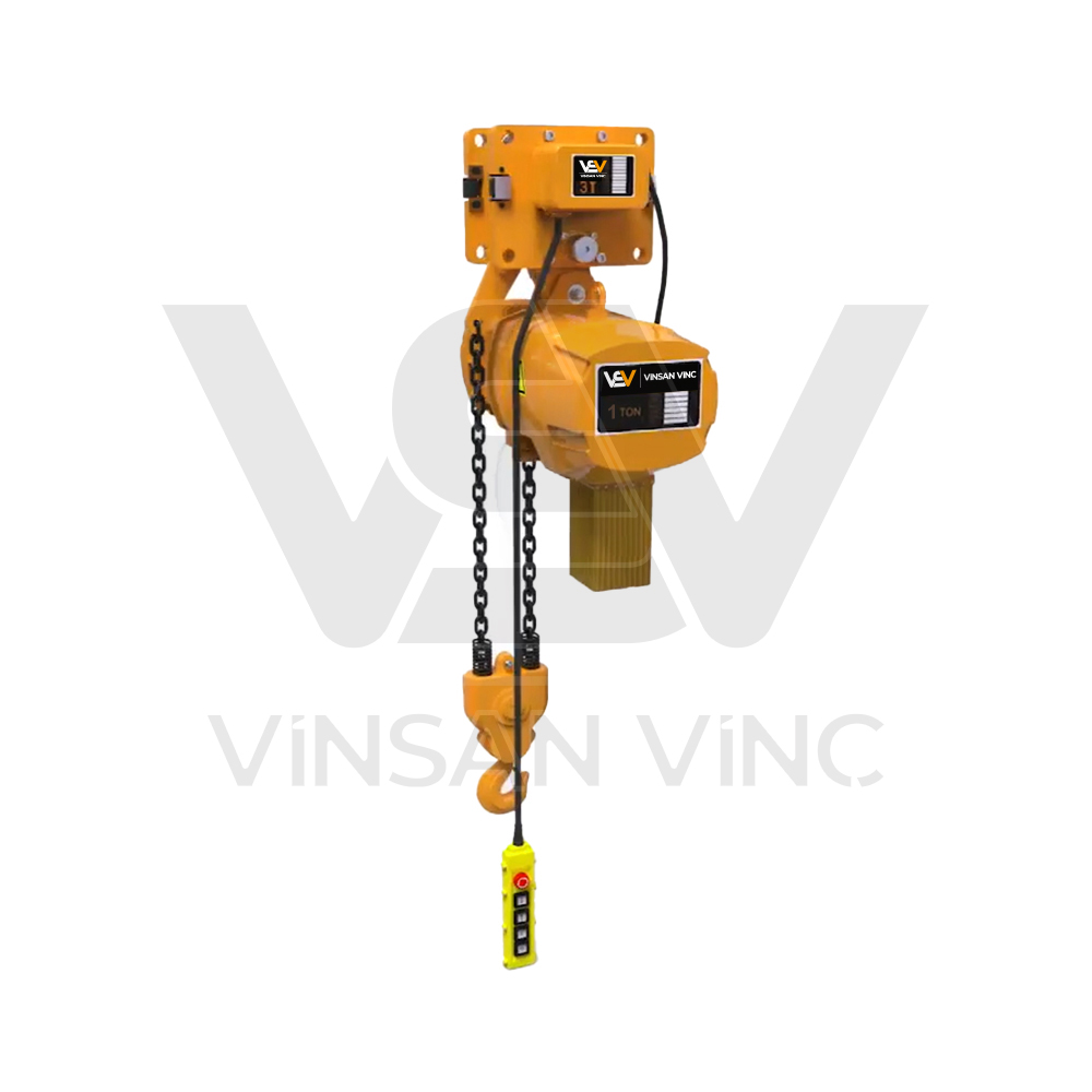
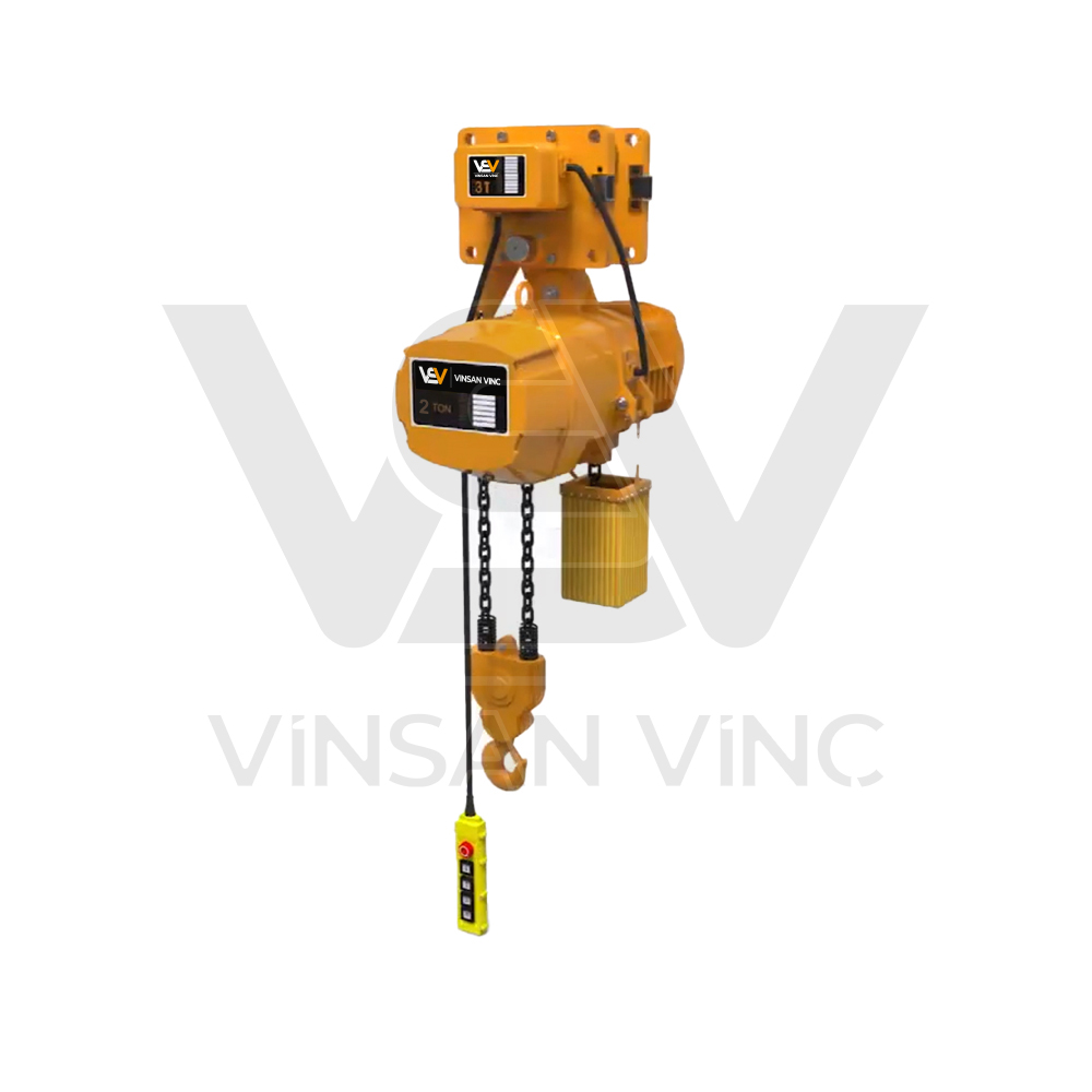
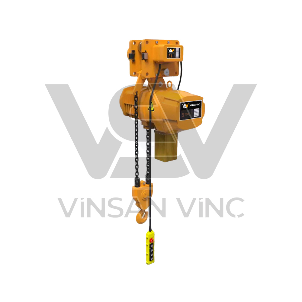
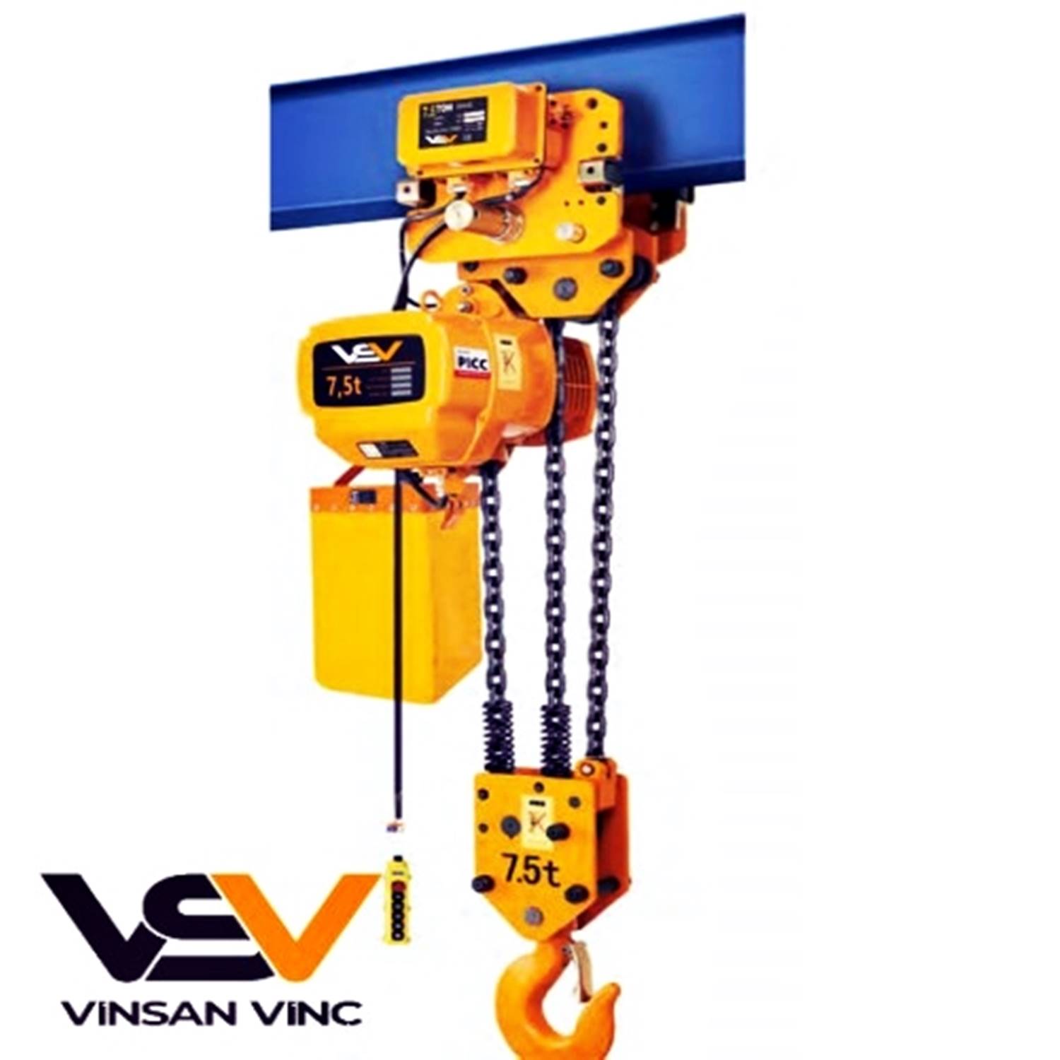
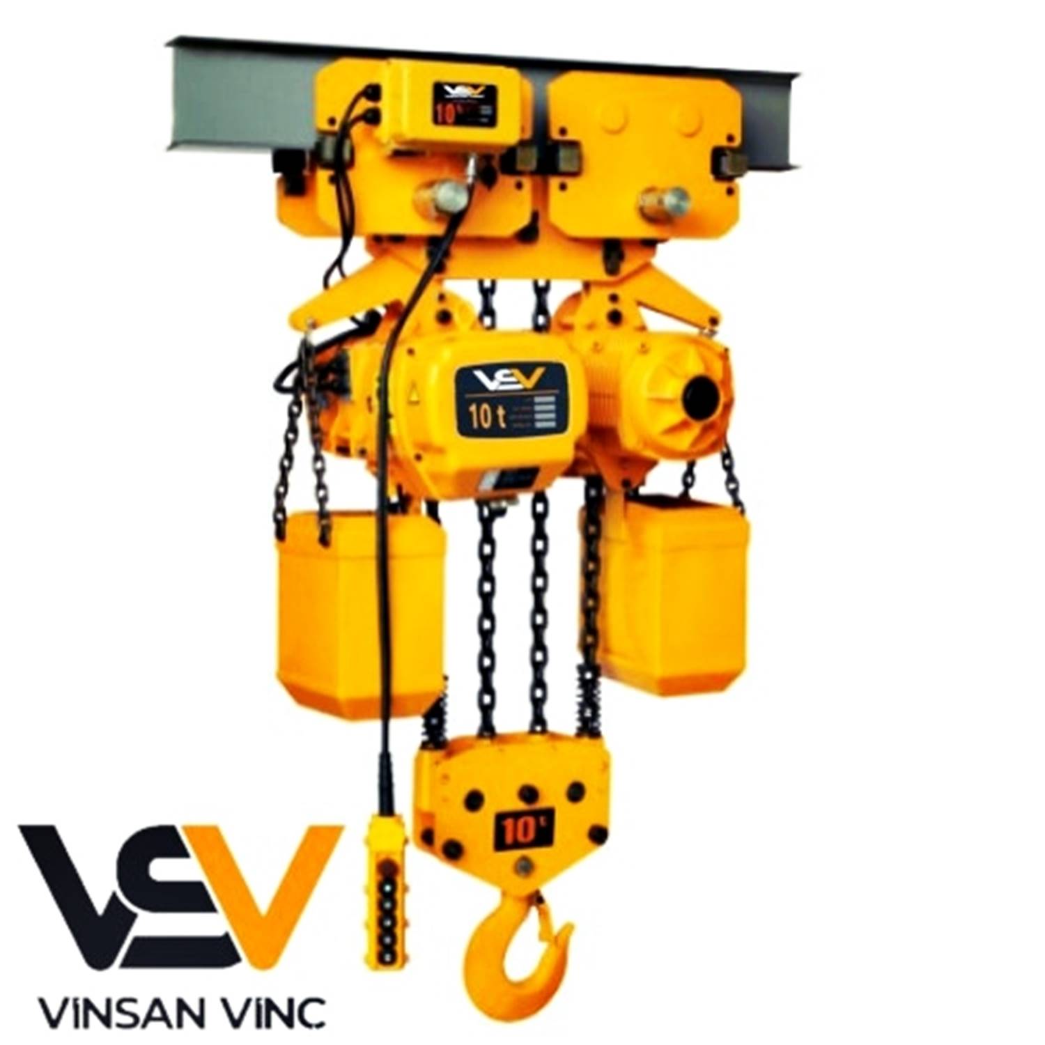
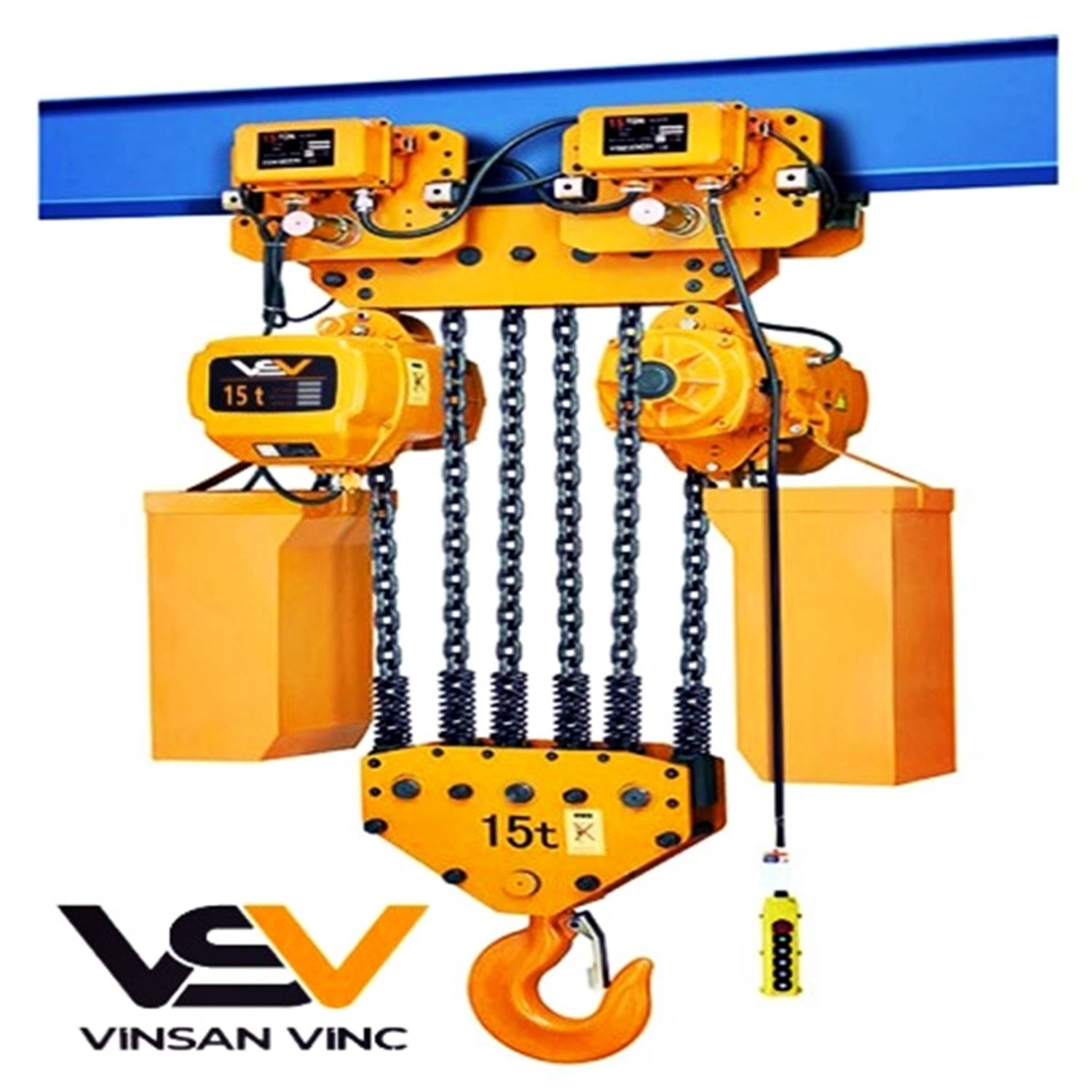
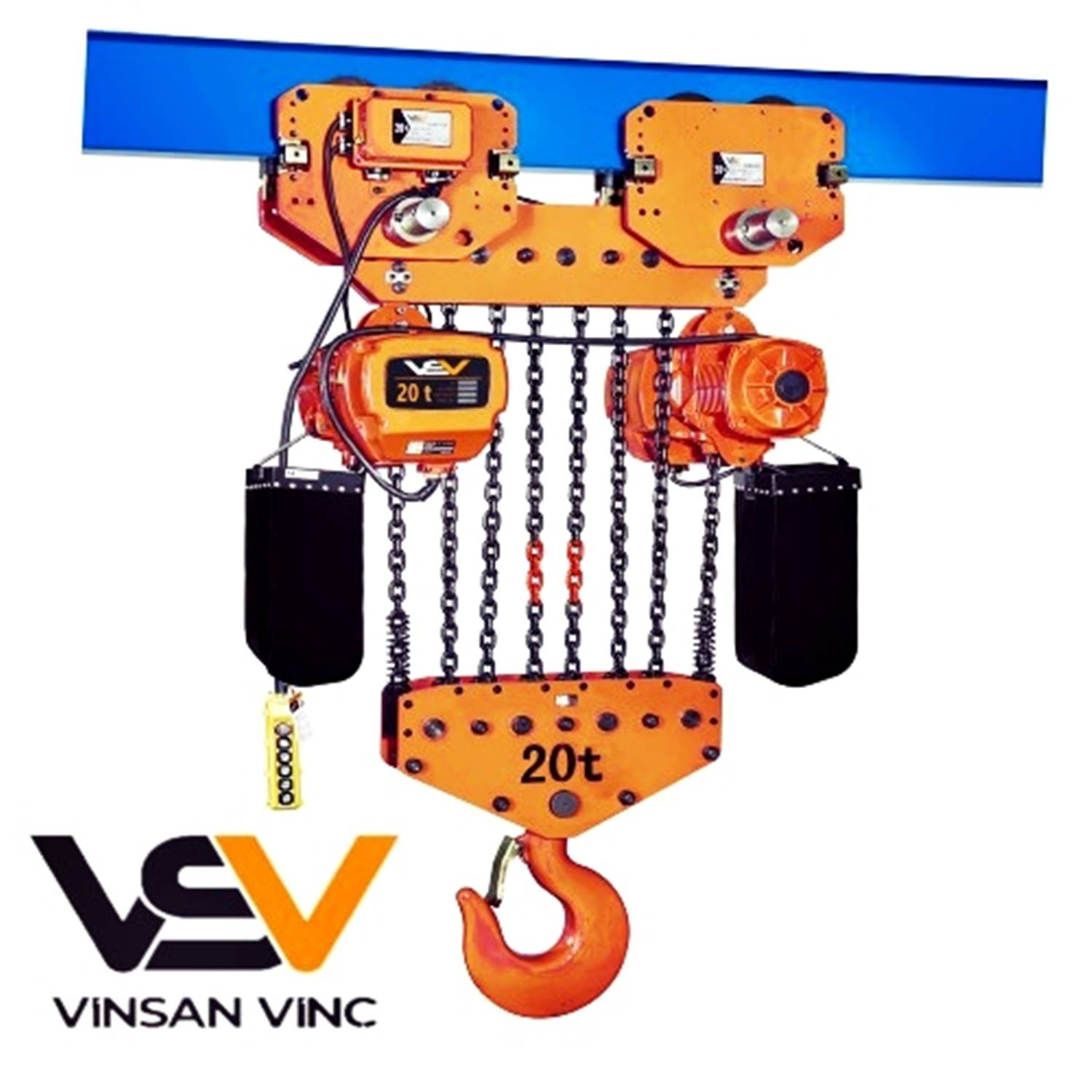
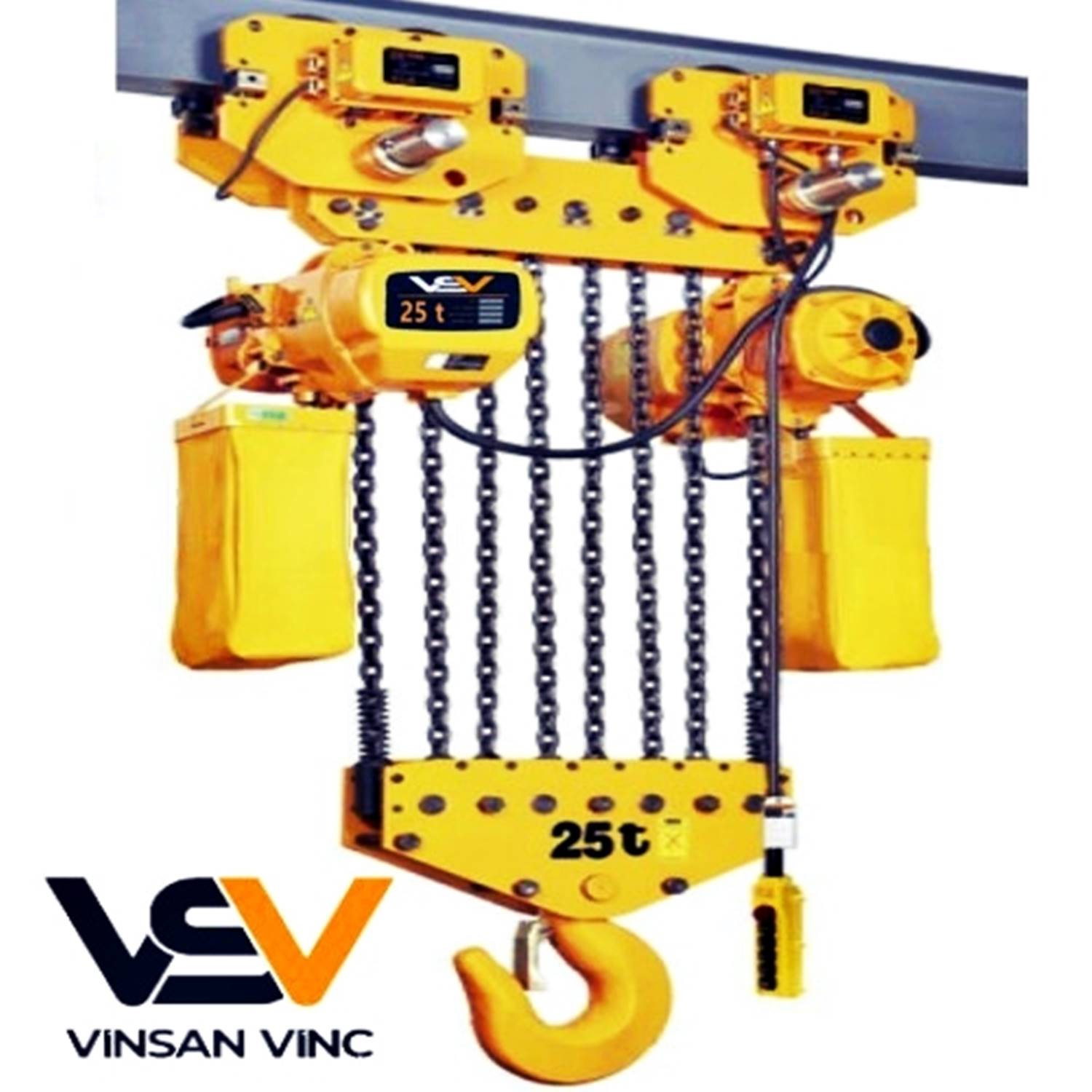
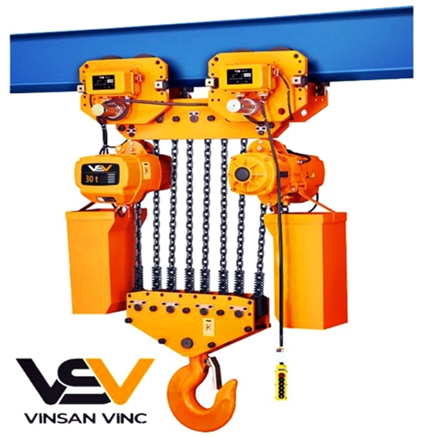
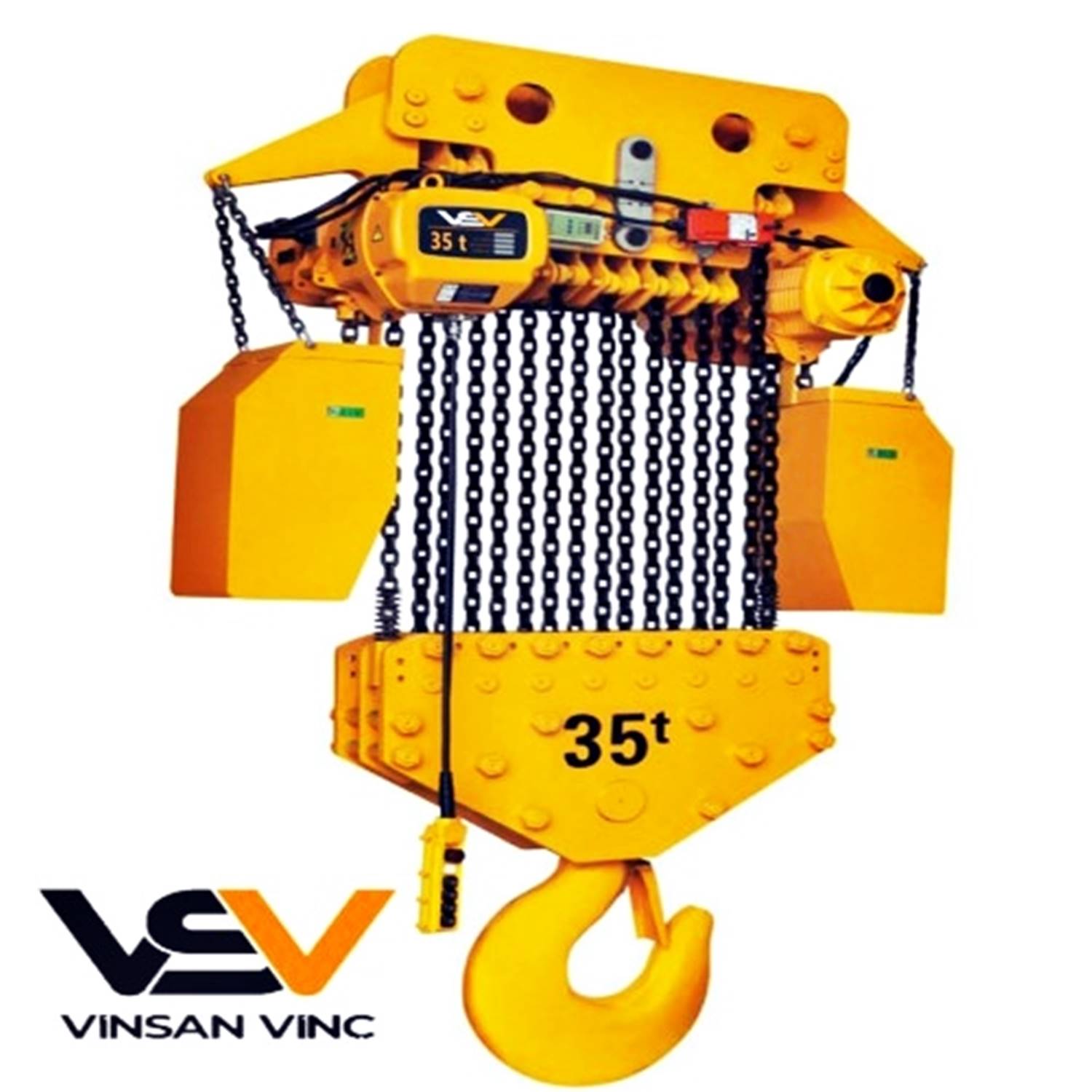
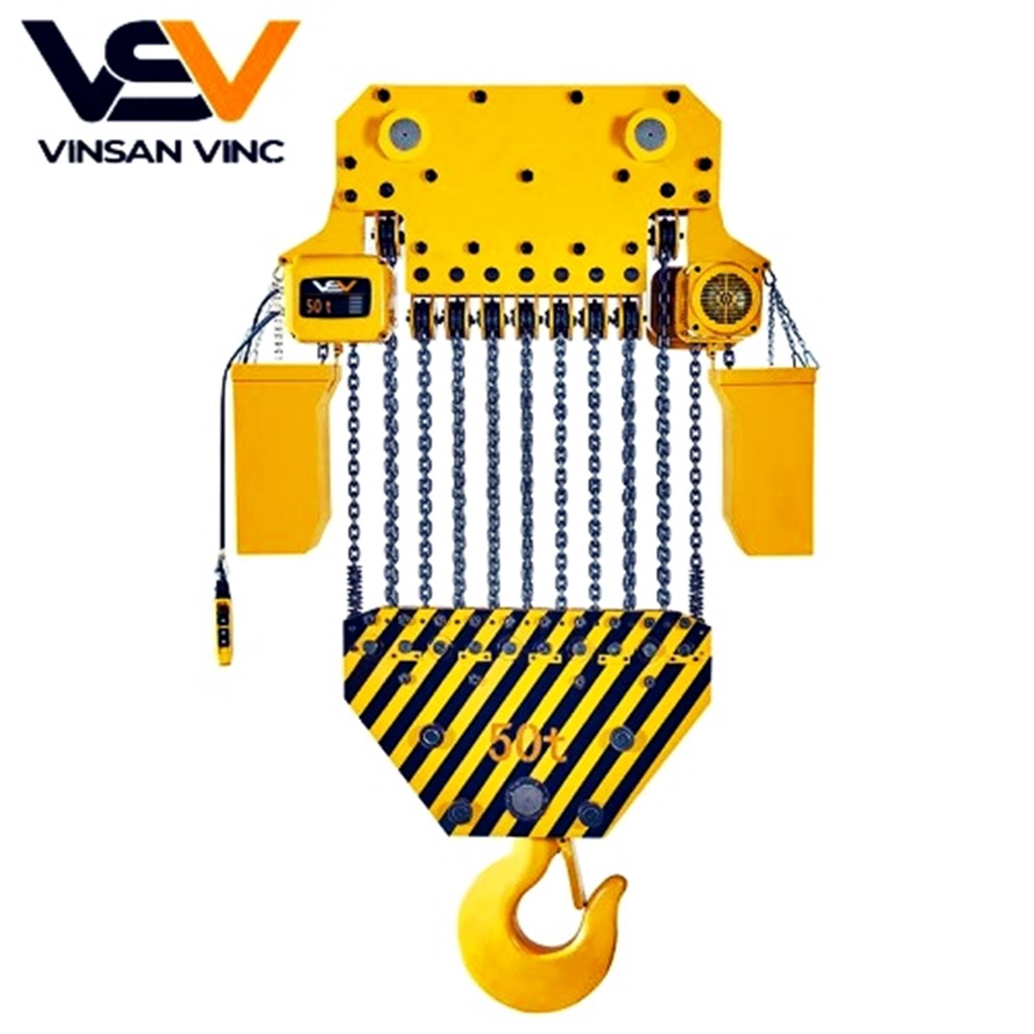
- Chain Hoist System: Chains are used in hand-operated hoists, walking drives and electric hoists in areas of use with low lifting heights. They are less preferred than steel rope systems in crane production. It is due to the disadvantages of chain hoist lifting systems, which are considered to be of high importance for the preference of lifting systems, compared to rope systems. They are used only at low speeds. Crane Systems Their own weight is higher than the load they lift, they are sensitive to impacts, their carrying power is high, they are more resistant to heat and corrosion.
- Crane Motors: Except for special cases, short-circuit asynchronous electric motors working with alternating current are the most preferred products due to their economy and ease of supply. In crane drive, direct current motors should be used according to the characteristics of the motor. Recently, the use of short-circuit asynchronous electric motors has increased with the use of frequency adjusters. The main features of crane motors that are required to meet the operational needs are as follows. In order to be able to lift heavy loads easily and to take quick action, the starting moments must be very large, they must be able to be processed frequently in short intervals in intense working environments. The eyebrows should be sensitive to the fulfillment of the opposite movement requests.
Things to consider when choosing a Crane Electric motor:
- To perform lifting and carrying functions,
- Simple and economical control and adjustment,
- Compliance with the construction economically,
- Compliance with operational safety,
- Advantageous in terms of maintenance and spare parts, etc.
Crane Drive System
Crane Drive Wheels
The types of drive wheels are listed below.
Double bandage wheels: (Figure 137/a) are generally used together with rail tracks and railway tracks in car and bridge walks. Most of the time, they ensure that the horizontal movements of the system they operate are limited according to the accepted tolerances.
Single banded wheels: (Fig. 137/b) are often used as I-profile rails, they are used on monorail cranes or as hoist trolley walking wheels.
Unbandaged wheels: (Fig. 137/c) are often used as guide wheels. Very rarely, it provides full horizontal movement.
Crane Drive Gearbox
As we wrote in lifting reducers, we will not explain the travel reducers in detail here.
For selection of travel reducer, the following information should be known:
- Output torque of the gearbox
- Output speed of the gearbox
- Input speed of the gearbox
- The ratio of the gearbox
- The overall efficiency of the gearbox.
Drive (Engine or hand)
Non-driven car: It consists of wheels with roller bearings on the chassis. By pushing the load, the system is enabled to run. Wheels are used in two double cars and four single cars.
Chain driven car: It consists of two wheels with bandage gears and two with normal bandages, which are bedded to the chassis with roller bearings. It is constructed in two separate trolleys with and without two-wheel drive, or as a four-wheel trolley. The gear wheels are connected to each other by the gear shaft which is supported by a roller bearing on the chassis. The walking of the system is provided by the chain pulled from the ground.
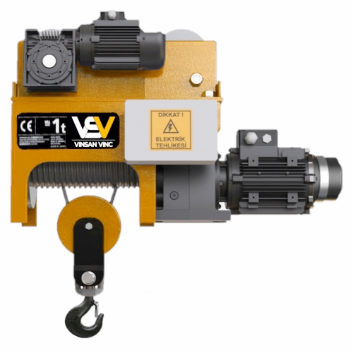
Electric motor driven car: It consists of two wheels with bandage gears and two with normal bandages, which are bedded to the chassis with roller bearings. It is constructed in two separate trolleys with and without two-wheel drive, or as a four-wheel trolley.
The gear wheels are connected to each other by the gear shaft which is supported by a roller bearing on the chassis. The running of the system is provided by being driven by a geared short-circuit motor with a pinion on the output shaft of a gear wheel.).
Crane Brake System
In order to respond to versatile demands, three groups of brakes have been developed according to their basic functions in cranes, more precisely in lifting and transport vehicles.
Holding and holding brakes: These are used to keep the load at the desired height while lifting and lowering it. While performing this function, they charge potential energy.
Travel brakes: These are used to stop horizontal movements. While doing this function, they are loaded with kinetic energy.
Lowering brakes: These are used to adjust the descent speed for vertical movements only. While performing this function, they charge potential energy.
Crane Command Control System
They are systems that work with 12 or 24 volt energy, which enables the determination of the movement directions of the cranes. It provides the crane-controlled motion determination by giving a command to the contactor located in the crane panels via the buttons on them.
There is an emergency stop button in the crane controls, in accordance with the emergency control and occupational safety rules. The task of this button is to disable the contactors in the panel when the command is given, and the movement is prevented.
Crane control systems can direct 2 – 4 – 6 – 8 – 10 or 12 different movements depending on the mobility of the crane they are used with; They also create an option for systems with double or single speed. Cranes can also be remotely controlled, or they can be manufactured with wired control depending on the working height.